Bending Guidelines
Sheet metal bending offers numerous advantages. It allows for the creation of intricate and complex shapes, enabling the production of customized components and products. The process is highly efficient, enabling fast production times and cost-effective manufacturing. Additionally, sheet metal bending provides structural integrity and strength to the formed parts, making them suitable for a wide range of applications.
File Checklist
Follow this quick checklist to ensure high tolerance bent parts. Each of these will be elaborated on below.
- Ensure minimum flange lengths are met
- Ensure critical features fall outside of distortion zone
- Exported as a 3D STEP file
Important:
Parts 3/16 or greater in thickness will be bent with a 4mm (~0.15") radius.
Use the chat bubble if you have any qestions about our process.
Material Table
See a full list of all bending materials and their capabilities.
| Grade | Thickness | Min Flange Length | Distortion Zone | Bend Radius |
|---|---|---|---|---|
No items. | ||||
Bending Capabilities
While we do have capabilities that extend beyond this list, following these guidelines will ensure the fastest lead-time and highest quality parts. If you have a part that does not meet these guidelines, please reach out to support@fabworks.com and we will do our best to accommodate your needs.
Thin Materials (<0.187")
- 1-135 degree bends
- 1mm (~0.039") Radius
- 3:1:0.75 minimum ratio for small (<3") reverse bends
- 4:2:1 minimum ratio for large (>3") reverse bends

Thick Materials (>0.187")
- 1-90 degree bends
- 4mm (~0.15") Radius
- 3:1.75:0.625 minimum ratio for small (<3") reverse bends
- 4:2:1 minimum ratio for large (>3") reverse bends

Tolerances
- Single bends will be held to a +/- .015" length tolerance
- Single bends will be held to a +/- 1 degree angle tolerance
- Features separated by multiple bends will be held to a additional +/- .015" for each separating bend
- Die marks will be visible on all bends
K-factor
In sheet metal bending, the K-factor is a crucial parameter that determines the amount of material elongation and deformation during the bending process. It is a constant value used to calculate the bend allowance, which helps determine the final dimensions of the flat sheet before bending. The K-factor takes into account factors such as material thickness, bend radius, and material properties to accurately predict the amount of stretch that will occur on the inner and outer surfaces of the bend. Incorrect K-factor can lead to unexpected part dimensions after bending.
Bend Radius
The bend radius is the radius of the arc formed on the inside of the bend. It is a critical parameter that determines the minimum size of the bend. Its important to change this value in your CAD software before exporting your file. Incorrect bend radius values can result unexpected part dimensions after bending.
Note:
Parts 3/16" or greater in thickness will be bent with a 4mm (~0.15") radius.
Minimum Flange Lengths
The minimum flange length is the minimum length of the straight section of material between the bend and the edge of the sheet. It's crucial to check and meet the minimum flange length requirements specified for the material and thickness being used. Refer to the material table above for the minimum flange lengths for each material and thickness.
Flange Length Calculator
Use this handy calculator to get a more accurate estimate at the minimum allowed flange length.
Note:
Distortion Zone
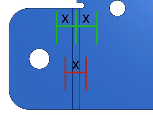
The distortion zone refers to the area of the sheet metal that experiences significant deformation and stretching during the bending process. It is important to identify and understand the distortion zone to ensure critical features, such as holes or slots, fall outside of this region. Placing critical features within the distortion zone can lead to dimensional inaccuracies or unwanted deformations, compromising the functionality and quality of the final part. Careful positioning of features outside the distortion zone is essential to maintain the integrity and accuracy of the bent sheet metal components.
The distortion zone extends out in both directions. It is NOT a single length centered on the bend line.

Important:
Do not hesitate to reach out to support@fabworks.com before placing your order if you have any questions.
Laser Cutting
Tolerances, kerf, taper and other guidelines for that are important to know when designing parts for our sheet metal laser cutting service.
Hardware
Hardware insertion is the process of installing PEM nuts, studs, standoffs, and other fasteners into sheet metal parts. These components are essential for the assembly of sheet metal parts and are often used to attach other components like PCBs, panels, and other sheet metal parts.